Advance Features
Advanced Tools
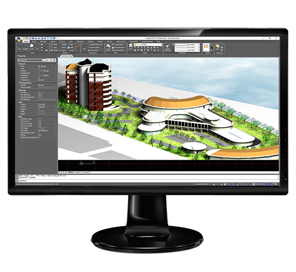
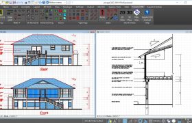
Make the most of your CAD software investment. Beside being an all-embracing 2D/3D CAD tool with all the fundamental drawing functionality, progeCAD offers professionals a large number of advanced features and exclusive tools
which are most likely to become indispensable in your CAD design arsenal.
The new BIM import features for Autodesk Revit® and IFC files expand the progeCAD usage for AEC market.
Any CAD User will appreciate to keep at hand and at no extra cost such tools as the PDF to DWG converter, the block management module, the vectorizer, PDF and 3D PDF export/import, multiple formats converters, the photorealistic render as well as some specific ones like topographic 3D Civil features and an architectural plugin.
The Swiss-Army-Knife CAD for file exchange
PDF to DWG conversion
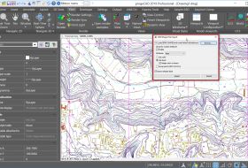
With the included PDF2DWG conversion engine, PDF Import is quick and easy. progeCAD helps you convert your PDF files to editable DWG drawings generating and optimizing vector entities such as lines, polylines, splines, hatches, circles, arcs and text strings. All colors are retained in the DWG/DXF file. PDF2DWG supports preview of pages, Batch conversion of all PDFs in a folder, multi-page PDF conversion, intelligent TrueType texts, line width and dashed lines recognition. PDFtoDWG is compatible with Layered PDF and preserves the same Layers scheme existing in the PDF when converting PDF to DWG. PDF2DWG allows to save time by easily transferring projects, drawings, parts of existing vector PDFs catalogs and manuals to CAD drawings to use them as native DWG files. PDFtoDWG supports all versions of Adobe PDF files.
With progeCAD, you can easily Import/Export into your drawings a large number of file formats:
IMPORT
- STEP, IGES Import (and Export) STEP geometries and transform them into easily editable DWG entities.
- SolidWorks Import .sldprt part files and .sldasm assembly files and transform them into DWG entities.
- ESRI-SHAPE SHP Import SHAPE (ESRI) files with geometry and its attributes into DWG drawings. Specific commands allow geometry insertion, colors and layers management, data dynamic control.
- Inserts geometries from SDF and SQLite. WFS services supported.
- 3DS, DGN(Microstation), LWO, OBJ(Wavefront), STL, RGT, DXF, DWF
- Autodesk Revit® to insert BIM models into DWG. .rvt/.rfa are standard the facto in the building industries. progeCAD allows inserting BIM Autodesk Revit® models into your DWG as an underlay or as part of the DWG.
- IFC to insert BIM models into DWG. IFC is a global standard for data exchange in the building industries. Building industry professionals can use IFC to share data regardless of what software application they use to get their job done. progeCAD allows inserting BIM models into your DWG as an underlay or as part of the DWG.
-
REVIT® - Direct import of Revit files (up to v. 2024) selecting the entire model or a specific View. BIM objects are placed on different layers selecting between two options:
1) Layers based on entities
2) Layers based on Level+Category.
If present, the appropriate materials will be associated with the imported entities. - POINT CLOUDS Import ReCap® .rcp, .rcs, and general formats like .pcg, .isd, .xyz, .ply, .las, .laz
EXPORT
- STEP, IGES
- IFC, with IFCEXPORT It is possible to include .rvt, .ifc underlays, and AEC Objects when exporting to .ifc files. Specify the IFC4 or IFC4x3 schema when exporting to .ifc files and set display properties for AEC styles.
- PDF, DWF, DWFx, 3DS, DAE (Collada), LWO, POV, MA(Maya), OBJ(Wavefront), BMP, JPG, WMF, EMF, SVG
- 3D PRINT STL Export for 3D Printer output

Advanced Blocks (Compatible with Dynamic Blocks)
Advanced blocks contain restrictions and rules controlling the aspect and behavior of a block when inserted into a drawing or modified.
One Advanced Block can replace many blocks. Combining multiple grips and actions allows you to create much smarter blocks.
One Advanced block may replace tens of the blocks you currently use and would therefore significantly increase your productivity.
Advanced Blocks (aka Dynamic Blocks)
. Transparently convert Dynamic Blocks to Advanced Blocks and moreover, using the block editor, you create and edit Advanced Blocks using parameters, actions, and visibility states as with AutoCAD® Dynamic Blocks. You can use it to modify any block reference and also make them parametric in size and shape. The contextual ribbon includes features to combine special grips and actions such as Move, Scale, Stretch, Rotate, Pattern or Mirror. You may, for example, create an Advanced Block which size can be dynamically adjusted with a grip that you can stretch.
You can also create Advanced Blocks with different states having hidden or shown elements. This allows, for example, to use only one block to show different options.
Convert Dynamic blocks into Advanced blocks
You can use dynamic blocks created with AutoCAD® as they are. They will keep their intelligence and parameters in progeCAD. When you edit (modify the Block
definition) an existing AutoCAD® dynamic block, it will be automatically converted into an Advanced Block.
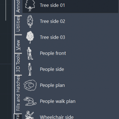
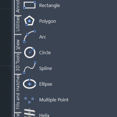
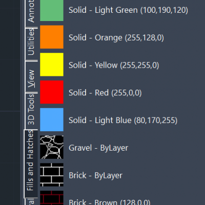
Toolpalettes for Blocks, Hatches and frequently used Commands
Use the tool palettes to organize blocks, hatches, and custom tools in a tabbed window. Easily customizable by Drag & Drop. Options and settings are accessible from shortcut menus.
The ready-to-use Palettes for:
Draw, Modify, Annotations, Utilities, View, 3D Tools, Fills and Hatches, 2D Architectural, Electrical Diagrams, Electrical Plants, Mechanics ANSI-ISO, Mechanics DIN-ISO, Hydraulic-Fluids and Pneumatics, Steel Sections
iCADLib module and Blocks Libraries
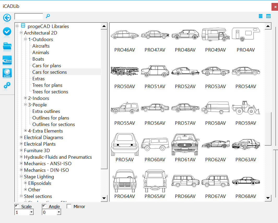
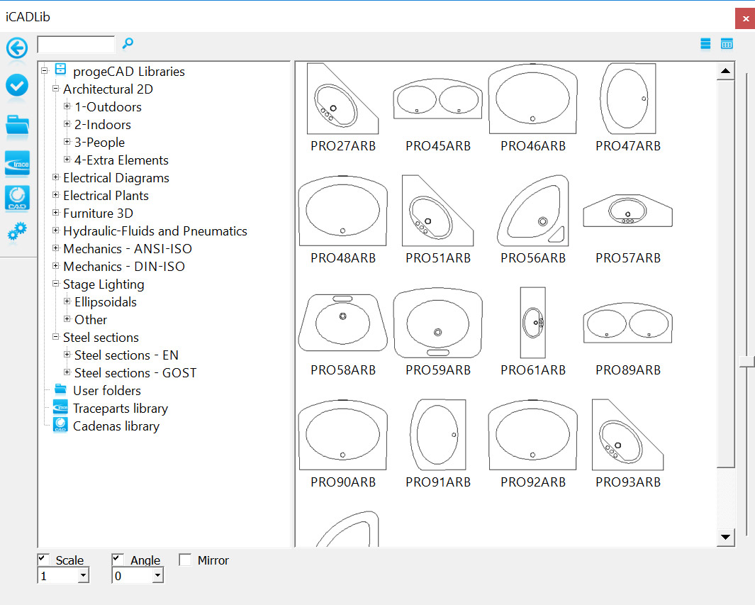
The advanced iCADLib module for blocks management ensures the best organization and management of your Symbol Libraries. More than 22.000 ready-to-use 2D/3D Blocks: Construction, Architectural, ANSI-ISO and DIN-ISO Mechanics, ANSI and IEC Electrical, Electronic, Steel Profiles, Furniture, Kitchen.
Traceparts, Cadenas and BIM&CO for progeCAD
iCADLib integrates Traceparts web portal, progeCAD's Cadenas web portal and BIM&CO web portal for easy guided usage of more than 100 million of
blocks CAD and BIM. Directly guided block insertion from the web into your drawings just in a snap. TraceParts and Cadenas are leading digital engineering 3D content companies offering cutting-edge business solutions through powerful web based products and services.
The Traceparts web portal and progeCAD's Cadenas web portal are freely available to progeCAD users worldwide with hundreds of supplier catalogs and 100 million CAD models and product datasheets suitable for design, purchasing, manufacturing or maintenance processes.
BIM&CO is the free of charge platform that sets the standard for BIM objects and high quality data.
PARAMETRIC 2D/3D LIBRARY - Imperial/Metric
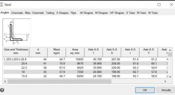
Parametric generation and insertion of 2D or 3D mechanical/structural components for construction using a dedicated interface:
- Wood: Lumber, Trus Joist® TJI®
- Steel: Angle, Channel, Tubing, Pipe, S-W-M-HP Shape, S-M-W Tee Shape
- Steel: Studs, Sstuds, Joist, Track
Two Tool Palettes for the new Structures library are provided, ready to use (Steel standard, Profiles and Wooden details)
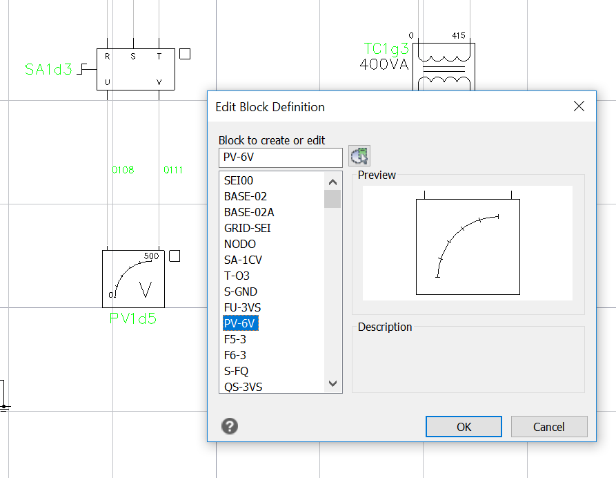
Block Editor (_BEDIT)
The Block Editor offers a special authoring area to enable free drawing
and editing of blocks geometry.
In the Block Editor, you can
Surveying, GIS and Civil Features
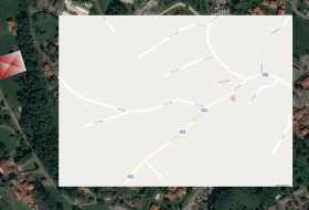
Geolocation with Bing Maps
You can insert geographic location information to a drawing file as a graphic background by specifying the location of a reference point on a map provided by Bing Maps service.
Geographic location information is assigned to a drawing file by capturing a portion of the Bing online map to an object known as a map image and embedding it to the drawing area.
Maps can be visualized as Aerial(terrain), Road or mixed.
Image Georeferencing
Georeferencing is the process of scaling, rotating, translating and deskewing the image to match a particular size and position. Special for GIS!
ECW support
ECW is an open standard wavelet compression image format developed by Earth Resource Mapping. The file format is optimized for aerial and satellite imagery, and efficiently compresses very large images with fine, alternating contrast. This is a lossy compression format.
MrSID support
MrSID (.sid), which is an acronym of Multiresolution Seamless Image, is a file format developed and patented by LizardTech for encoding of georeferenced raster graphics such as orthophotos. The MrSID (.sid) format is supported in major GIS applications such as Autodesk, Bentley Systems, CARIS, ENVI, ERDAS, ESRI, Intergraph, MapInfo and QGIS.
Jpeg 2000 support
Jpeg 2000 is a wavelet-based image compression standard. It was created by the Joint Photographic Experts Group committee in the year 2000 with the intention of superseding their original discrete cosine transform-based JPEG standard.
ESRI-SHAPE Import
Import SHAPE (ESRI) files with geometry and its attributes into DWG drawings. Specific commands allow geometry insertion, colors and layers management, data dynamic control.
MAPIMPORT - Geo Data and FDO Import
Inserts geometries from SDF files (SDF is a native Autodesk® geospatial file-based format optimized for storing large classified data sets), SQLite and SHAPE (esri) files, or can use a database server service like WFS (the Web Feature Service allows users to share geospatial /or non-spatial data over the Internet. Thus, feature services can be consumed through the Internet in WebMaps, desktop and web applications.), PostgreSQL or MySQL.
MAPIINSERT - Multiple images insertion
Insertion of multiple images at the same time (especially useful for georeferenced images).
RUBBER SHEETING
Tool for image editing (Raster Design). Use rubber sheeting when you want two or more different data sets from different sources to align geographically: for example, when stretching a new subdivision map into a preexisting parcel map. Rubber sheeting is a nonuniform adjustment of a data set based on the movement of known control points to new locations. For example, data collected by aerial survey may be inaccurate because of flight alignment and camera inaccuracies. By comparing these data with the accurate ground survey data, the aerial data can be stretched or rubber sheeted over the accurate data using control points and objects common to both data sets.
3D and 2D Civil Features
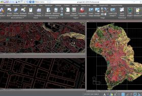
Fast triangulation of point clouds Creation of TIN surfaces from points within point cloud scan files or land survey collected points. AUTOSEZ command can be applied to these surfaces.
AUTOSEZ The tool for the automatic creation of surface profiles to show surface elevations along a horizontal alignment to represent, for example, road edges or ditches (Topographic Sections)
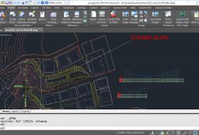
SLOPE The tool for an easy creation of terrain slope lines (ticks) between two edges or for a conversion of polylines into slope-style polylines.
3D AEC Architectural module - The Architectural 2D/3D plugin
The automated building tool for architects is designed to increase productivity.
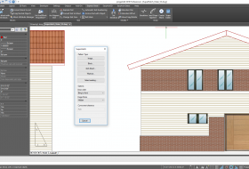
Compatible with AutoCAD®AEC Objects (AutoCAD Architecture®). The new AEC package allows you to draw 3D architectural elements with a two-dimensional view in plan and takes advantage of a whole series of new Architecture style commands. The drawn entities are now specific AEC elements editable and configurable via the Styles management. By default, it replaces our previous EasyArch architectural plugin which still remains available and can be activated with the variable AECMODE.
Main Features:
- Draw walls, doors, curtain walls, windows, stairs and railings
- Draw slabs, roofs, or roof slabs
- Walls and Slabs can be created by direct conversion of 2D entities
- Multi-level manager to assign levels to AEC entities.
- AEC Styles manager: manage & customize AEC Styles for Walls, Doors, Windows, Curtain Walls and Curtain Wall Units, stairs and railings, and slabs
- AEC Family – imports AEC objects style from external fam or dwg files
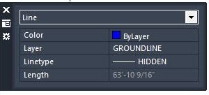
QUICK PROPERTIES Palette
The Quick Properties palette shows a list of object properties for one or more selected objects. Rapid access to the most useful object properties avoiding irrelevant and confusing fields. You have the Quick Properties palette beside the cursor when clicking on an object.
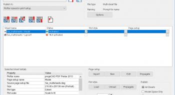
Publish (Batch Plot)
Layouts taken from one or more drawings can be printed or exported to PDF or DWF using the print settings of individual layouts. Speed up the print process when necessary to print or export several different drawings or drawings with several different layouts.
QRCODE
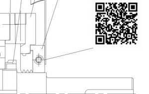
Create and insert a QRCODE from any text, URL etc.
Make text in your drawings scannable from QR Codes using any mobile phone or tablet with a camera.
QR Codes, also known as mobile barcodes, allow to represent text, URLs, contact information etc.
Users may get automatically a lot of useful information for execution of maintenance, simply scanning the QR Codes visible in the drawings.
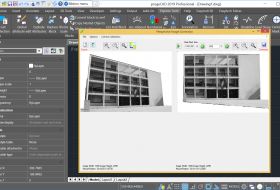
Perspective Image Correction
Thanks to this plugin, photos insertion is easy and intuitive, with the ability to correct their perspective through the multi-point system.
Generative AI Drawing Translator
Translate drawings to any language at a glance!
Powered by Generative AI, the new progeCAD text translator for drawings, uses the translation engine by Google® AI to translate all or part of your drawing, into any language. The translated texts do not change their nature, therefore the drawing remains compatible with all CAD-DWG software.
It works on Text, Mtext, Block attributes, Mleader, and Tables.It works on Text, Mtext, Block attributes, Mleader, and Tables.
Advanced Render - ARTISAN
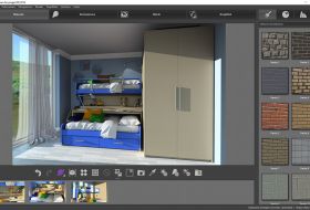
This is an ideal product for architects, engineers and for all those designers who need to view their own drawings in a photorealistic visualization.
progeCAD professional includes for free the advanced Artisan Renderer Engine based on the ray-tracing algorithm. It allows you to quickly create a photorealistic image of your model using a wide range of pre-set materials and lighting setups combined with the ability to create custom lights and realistic materials. It has the following characteristics:
- Photorealistic rendering with light and shade, reflection and transparency effects
- Materials like wood with grain, stone, plastic, metal, bricks (customizable, different shades)
- The finishing can be personalized with effects of reflection or transparency
- Complete control over illumination thanks to multiple light points
- Library of pre-set materials
- Smooth shadows
- Sun position control
- Save images with a custom resolution
- Pre-defined lighting schemes
- Library of pre-set backgrounds, 2D and 3D (hemispherical image)
- Manage SnapShots, for storing all the data from your work in scenes
- Archives of own libraries of materials, lights and backgrounds.
With progeCAD you can also easily export drawings to other external Rendering software like: LightWave (.lwo), 3dStudio (.3ds), Pov-Ray (.pov)
Gradient Hatch Support
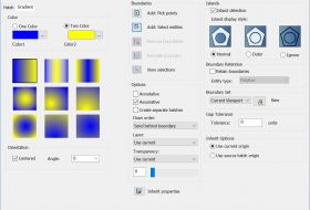
Fleshing out a drawing on progeCAD can give it additional impact during presentations, and the addition of color gradients to surfaces to produce a more "realistic" appearance is a great way to do so.
Gradients can be displayed and created through a user-friendly interface. Improved Hatch Form.
Color Books
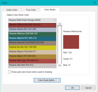
progeCAD supports standard Color Books
With progeCAD, the RGB values of the Color Books Colors that are assigned to objects are preserved in all current and legacy drawing files
Annotative Objects
The feature automates the sizing of annotations such as text, hatch and
dimensions in multiple viewports with varying scales.
The annotative objects are scaled based on the current annotation scale setting and are automatically displayed at the correct size. The following objects can be annotative, meaning that they can size automatically:
Tables
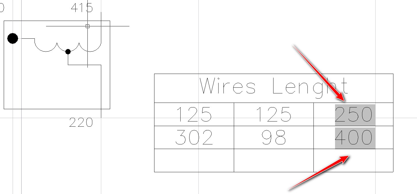
A table is an object with information arranged in rows and columns. Similar to spreadsheet, the rows and columns can be adjusted with grips, and styles can be assigned to the table and to selected cells.
progeCAD supports dynamic and static linking of tables with Excel worksheets.
progeCAD Tables support AutoCAD® like Text in-place editing, numeric Rows and alphabetical Columns.
Table Cells can contain formulas that do calculations related to the values in other Table Cells.
With a Double-Click on table cells, you can insert formulas from the Table Cell Editor.
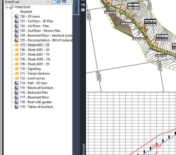
Sheet Set Manager
Any design project requires a set of drawings and specifications to accompany the report which specifies the scope of the design. progeCAD Sheet Set Manager is an amazing tool to manage your drawings from start to finish in your design.
Using sheet sets in the most basic way you are just taking drawing files and organizing them in proper order, so they can be easily retrieved when working through your project.
Sheet Sets improve your team collaboration, facilitating working on one subset while you work on another.
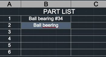
Spell-check on the fly
Multiline text, Multileader and Tables text is automatically checked for spelling while typing, underlining wrong words.
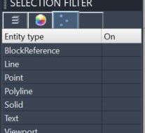
SELFILTER
Controls the Selection Filter panel. It displays all entities in the drawing and allows you to filter and select entities by Layer, Color, entity Type and Linetype.
When you finish selecting entities, you can then use the selection set in subsequent commands.
Construction Lines
A Construction Line is a special type of the infinite line that is typically used when quick drafting techniques are required.
Similar to the infinite line, the construction line is a line through a given point, oriented at a specified angle in the three-dimensional space and extending to infinity in both directions
Point Clouds
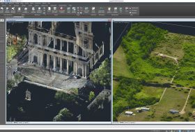
A point cloud is a collection of points acquired using 3D laser scanners or other special technologies to create 3D representations of existing structures.
Point cloud files help the design process by providing real-world context where you can recreate the referenced objects. Once a point cloud is inserted to a drawing, you can use it as a guideline for the drawing, change its visualization, or apply a color to distinguish different features.
Along with the standard ReCap® .rcp/.rcs file formats, with progeCAD you can import Point Cloud formats such as PCG, ISD, XYZ, PLY and LAS
3D PDF Export
Create the ADOBE PDF standard with your dynamic 3D content inside.
3D PDF allows to communicate to all the globe and share your data with anyone in an easy and innovative way. Smart collaboration with your draftsmen and designers as well as users who do not deal with CAD software.
3D PDF can be visualized with the free Adobe® Reader®/Acrobat Reader DC software.
Superhatch Command
Create hatch patterns from images, blocks, external references ( xrefs ) and wipeouts.
Superhatch is an express tool function that lets you quickly hatch with your own pattern, no programming or creation of pat files needed. progeCAD's hatch with image capability is a part of the Superhatch function.
progeCAD Cloud
Cloud services will reshape the consumer digital lifestyle experience, with progeCAD save and open drawings on Cloud! progeCAD Cloud makes it easy for you to reach any of your drawings wherever you are.
What is more, it is an optimal way of sharing drawings with your team and customers. progeCAD Cloud supports the major cloud services for file sharing and syncing like DropBox, Google Drive, and Microsoft One Drive.


ACIS Solids
Reads and writes 3D solid objects with ACIS libraries (the same as AutoCAD®). ACIS solids are available thanks to an agreement signed with Spatial, the supplier of technology for solid modeling to the most important CAD software in the world. progeCAD Professional has implemented a complete management of ACIS solids, which can now be viewed, printed, created and edited.
Any exchange of projects with CAD, which include ACIS Solids, is therefore much easier! Creation of complex three-dimensional shapes using solid models becomes a way simpler procedure.
DATAEXTRACTION and Microsoft Excel Integration
Extracting information from objects such as block attributes and drawing properties and creating a detailed schedule, a parts list, or a bill of materials to a table inside a drawing or into an external file. For example, with a residential construction project, create a door installation schedule to place in the drawing. Using the Data Extraction wizard, you can limit the selection only to doors objects and extract the data.
You can create a list as an Excel external file as well. You can use a data extraction file as a template to perform the same type of extraction at any time.
Dynamic CAD Tables
DATAEXTRACTION can create CAD tables, dynamically linked to the drawing and automatically updated with drawing changes through the DATALINK functions.
DATALINK
Link a Microsoft Excel spreadsheet to a progeCAD table dynamically linked to the external file. The best thing about data linking is that any changes that you make to the Excel spreadsheet will update the progeCAD table. Plus, if you set it up this way, you can edit the table and it can write back to the spreadsheet.
XLSIMPORT
Imports directly an .xls or .xlsx file into a new static progeCAD Table.
The imported data fill a new table that is created automatically during import, and the new table is formatted automatically to match the format of the original spreadsheet.
Dynamic Input
Dynamic Input is an alternative way of entering commands through a command line interface at your Crosshair. You can input data like the length of a line or the radius of a circle with dynamic visualization of changes relative to mouse movements. When dynamic input is turned on, a tooltip displays dynamically updated information next to the cursor. When a command is in progress, you can specify options and values in the tooltip text box. You can also configure dynamic input to meet your personal or company standards. The feature is to further boost your productivity by making drafting and editing processes way more efficient.
3DCONNEXION Support
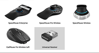
All powerful 3DConnexion mouse and devices are supported, with contextual menus and options.
Compatible with BetterWMF
BetterWMF solves problems related to copying and pasting drawings into other software packages like Microsoft Word.
If you have ever tried to insert a CAD picture into for example a Microsoft Office document you may have noticed several problems: To start with, you will get unwanted borders. The resulting size of a picture is the same as the graphics area of the CAD window at the time of creation, rather than matching the selected objects. This usually means that pictures copied from progeCAD to other Windows applications will have a large blank area to the top or right. Also when you print the document with the picture you will notice that all lines will become equally (very) thin. Finally, you will have discovered that it is very difficult to size your picture to an accurate scale.
For each of these problems individually, clumsy workarounds are possible, with varying degrees of success. The unique real solution is BetterWMF.
Learn More...
progeCAD is fully compatible with the BetterWMF version for AutoCAD LT but providing all the features available with the version for AutoCAD Full.
Express Tools
progeCAD Express Tools is a set of tools mainly grouped under the Express Tools menu which extend progeCAD functionality enabling the user to increase productivity through easy, fast and efficient performance of complex multistep CAD operations.
Digital signatures to DWG
The digital signature certifies the author of a file and indicates whether the file has been altered since the digital signature was applied.
Recipients of drawings are provided with reliable information about the author of a drawing.
Owners of drawings are provided with reliable verification that a drawing has not been modified since it was digitally signed.
And more
RASTER HANDLING (See Video)
Insert and manipulate Raster images with only one click of the mouse!
With the powerful raster editing and raster-to-vector conversion tools, progeCAD helps you to easily clean up, edit, enhance, and maintain scanned drawings and plans. Use a wide range of image data, embed images, insert and export images and use a polygonal mask boundary to display image subsets. Image transformation functionality and georeferenced image display.
RASTER TO VECTOR CONVERTER
progeCAD Professional includes a free version of WinTopo, the raster to vector tool, which main functions are:
- Loads BMP Bitmap images (raster)
- Refines bitmap lines and detects the edges
- Creates monochromatic vectors from refined lines
- Views vectors on top of the bitmap
- Load vectors to progeCAD, IntelliCAD, AutoCAD
DYNAMIC UCS
The dynamic UCS feature automatically creates a temporary XY plane to draw on. The dynamic UCS feature dramatically speeds up drawing in
3D environment.
MULTILINE
The multiline command allows
to draw multiple parallel lines with a single command. This feature creates simultaneously perfectly parallel lines and the lines are treated as one entity allowing easier editing. The Multiline support greatly speeds up and simplifies drawing and improves the AutoCAD® compatibility. Multilnes Styles supported.
MULTILEADERS (See Video)
The MLEADER command can create leaders with a variety of arrows, segments and
content, including text and blocks with attributes.
NUMBERED MARKERS (Bubbles or Balloons
)
Automatically creates bubbles with sequence numbers or letters.
INCREMENTAL SAVE
It updates only those portions of an already-saved drawing file that you've changed, improving the Save time.
When you use incremental saves, drawing files will contain some wasted space. Each incremental save increases this percentage until it reaches a maximum percentage, specified by the Variable ISAVEPERCENT, at which time a full save is performed instead.
POINTS IMPORT
Imports 2D-3D points with specified coordinates from a .txt or .csv file into a drawing.
Points can be imported as separate point entities, as vertices of a polyline, or as vertices of a spline
ADDSELECTED
Create a new object of the same type and general properties (Layer, Color, Linetype etc.) of a selected object, yet with different geometric values.
AREATEXT
Calculate boundary area and place the text with the value in the center of the area. Through the configuration dialog the user can set: Units used for drawing, Units desired for measurement, Prefix, Suffix Units of measurement, Decimal number, Retain boundary. It is possible to select an area through multi points, the direct selection of entities or by clicking inside a closed area.
SPLINE EDITING
You can delete fit points of a spline, add fit points for greater accuracy, or move fit points to alter the shape of a spline. You can open or close a spline and edit the spline start and end tangents. The spline direction is reversible. You can also change the tolerance of a spline. Tolerance refers to how closely the spline fits the set of fit points you specify. The lower the tolerance, the more closely the spline fits the points.
MULTIGRIP EDITING and ADVANCED SOLID GRIPS
Modify, move, rotate, scale, stretch or mirror using multiple Grips
By dragging grips you can change the shape and size of primitive solids. For example, the change of the height of a cone will maintain the overall cone shape and automatically update the base radius. The Solid Grips feature is introduced to enrich 3D editing operations.
LOFT COMMAND
The loft command is similar to the extrude command but much more versatile. Instead of extruding a single shape, the loft command allows you to extrude several shapes and make one continuous object.
FLATSHOT COMMAND
Creates a 2D representation of a 3D solid object based on the current view of the solid object. An entire drawing can be flattened with a single operation.
HELIX COMMAND
Draws a custom 3D Polyline in the form of a helix
progeCAD 2026
progeCAD, is an AutoCAD® compatible 2D/3D CAD application that works with AutoCAD® DWG files from AutoCAD® 2.5 through AutoCAD® 2026! The ideal solution for AEC, MCAD and all generic CAD usages. ACAD alternative. Learn More...
Familiar Interface
The progeCAD interface will make you feel comfortable from the very beginning. progeCAD offers both AutoCAD® compatible Classic and Ribbon icon interfaces and a complete set of AutoCAD® compatible commands. Learn More...
Comparison
progeCAD offers all the main features available with AutoCAD® and is also renowned for its handy extra tools added for free to further boost your productivity. Your cost-effective drawing power, ACAD alternative! Learn More...
Flexible Licensing
progeCAD Professional is available with different perpetual licensing solutions, suitable for all business dimensions, from a single drafter to global corporations. Learn More...
progeCAD 2026
CAD Alternative
progeCAD Professional is a 2D/3D DWG-native CAD for general-purpose drafting. The program offers very high compatibility with AutoCAD®, yet progeCAD is way much more than just an alternative to the market leader. progeCAD integrates its exclusive tools and sells with PERPETUAL LICENSES at a fraction of the cost of industry leaders.
High Compatibility
progeCAD's original format DWG ensures complete compatibility with AutoCAD® WITHOUT ANY FILE CONVERSION and without losing any critical information. progeCAD offers the interface complete with the "AutoCAD® - Like" Classic icon and Ribbon menus and "AutoCAD® - Like" commands.
